A couple of weeks ago there was a local advert for a vintage Tandy 1000RL computer in very minty condition. I picked it up, primarily because I was interested in the rather old school monitor it came with (a Tandy RGB-11). While not as flat out brilliant as the Commodore 1081 I used to own in Europe a couple of years ago (usable for many purposes), it’s still a pretty respectable vintage display device in it’s own right.
These CGA monitors accept a fairly simple, digital (TTL) type signal. When looking at the pinout, it’s fairly easy to see why this signal is often referred to as “RGBI”.
| Pin | Name | Description |
|---|---|---|
| 1 | GND | Ground |
| 2 | GND | Ground |
| 3 | R | Red |
| 4 | G | Green |
| 5 | B | Blue |
| 6 | I | Intensity |
| 7 | RES | Reserved |
| 8 | HSYNC | Horizontal Sync |
| 9 | VSYNC | Vertical Sync |
I picked up on the idea of driving the screen directly with a stock Arduino (UNO), without additional hardware. While researching the subject I found this very interesting blog post from 2011 which demonstrated a proof-of-concept for driving a CGA screen (displaying a fuzzy Hungarian flag in the process). Although this post made for a good initial starting point, the code needed to be improved and added upon considerably (since it is only able to emit 3 large, jittery horizontal color blobs).
Wiring up and stabilizing the video output
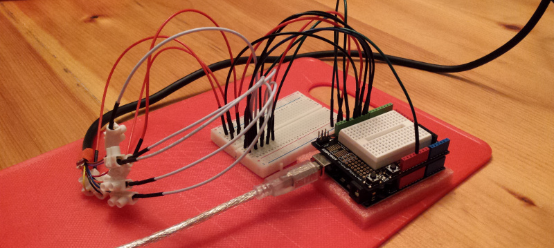
Wiring the Arduino to the CGA connector is very straightforward (through a prototyping breadboard).
| CGA connector | UNO |
|---|---|
| GND | Ground |
| GND | Ground |
| R | Digital Pin 8 |
| G | Digital Pin 9 |
| B | Digital Pin 10 |
| I | 5V |
| RES | N/A |
| HSYNC | Digital Pin 11 |
| VSYNC | Digital Pin 12 |
CGA has a horizontal frequency of 15.75kHz (with screens typically a bit tolerant of timings which are close). This means we have to emit a single horizontal line in approximately 63.49 μs.
As the electron beam travels the screen, for every line we will advance through the following phases:
- left blanking
- left overscan
- emitting a number of pixels (for each pixel, writing a nibble of information to r, g, b, i)
- right overscan
- right blanking
- pulling HSync high
Since the ATMega328P runs at 16Mhz (with a single CPU cycle taking 62.5ns) we have approximately 1015 CPU cyles to work with per line.
Once we have a firm sense of timing requirements, we need to apply some tricks in order to generate and stabilize the video signal:
Disabling interrupt handling
Built-in Arduino interrupt handling (gravely) interferes with the timing of the generated signal (when performed in the main loop). In order for the image to be stable rather then jittery, we will disable interrupt handling. Please note that this also disables serial communication.
noInterrupts();Note: alternatively, one could implement the actual drawing of the screen inside an interrupt handler.
Using direct port writes
The nice digitalWrite abstractions (as provided by the Arduino libraries) are way too slow to be usable for our purposes. Although less portable, we will have to resort to
direct port manipulation in
order to conserve (much needed) CPU cycles, e.g.
#define SETC(x) PORTB = (PORTB & ~7) | xPadding it out with NOPs
We will need to count CPU cycles carefully and pad out our phases with inline assembly NOP instructions (to arrive exactly at the desired timing).
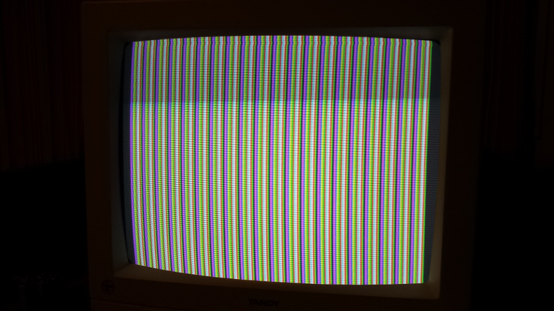
#define EXEC_NOP asm volatile ("nop\n\t")Once we have all of this in place, we are able to generate a stable CGA signal, as the code in this gist demonstrates (8 colors, horizontal resolution: 200 pixels, with a single line of pixels repeated vertically).
Implementing a framebuffer
The main limitation if that we only have 2kB of RAM. With a resolution of 200x200 (otherwise techically perfectly feasible, as demonstrated above) we would need a whopping 40kB of RAM if we use a single byte to represent a pixel. Even denser packing schemes (3 bits per pixel) would require far more then what we have available.
We have no other option than to emit the signal on time. Denser packing schemes will put a lot of stress on our ability to deliver any kind of meaningful horizontal resolution. For the
same reason, reading from flash with pgm_read_byte is not an option for us here.
We will move to a monochrome - only signal. We’ll interpret every single bit as being an “on” or “off” pixel exclusively, and put that towards the green channel only. The extra (quite minimal) bit-shifting that is now required (in order to extract the individual bits in a byte) has a big impact CPU cycle wise. Our usable horizontal resolution is halved (leaving us at 100 pixels).
The following snippet shows how two bytes from the framebuffer (16 pixels) are being fed to our main pixel “pipeline”:
...
SETC((buf[i][0] >> 7) & 1);
SETC((buf[i][0] >> 6) & 1);
SETC((buf[i][0] >> 5) & 1);
SETC((buf[i][0] >> 4) & 1);
SETC((buf[i][0] >> 3) & 1);
SETC((buf[i][0] >> 2) & 1);
SETC((buf[i][0] >> 1) & 1);
SETC((buf[i][0] >> 0) & 1);
SETC((buf[i][1] >> 7) & 1);
SETC((buf[i][1] >> 6) & 1);
SETC((buf[i][1] >> 5) & 1);
SETC((buf[i][1] >> 4) & 1);
SETC((buf[i][1] >> 3) & 1);
SETC((buf[i][1] >> 2) & 1);
SETC((buf[i][1] >> 1) & 1);
SETC((buf[i][1] >> 0) & 1);
...
In order not to skew the image too much (as far as diverging from a typical aspect ratio is concerned) - and to save on precious RAM once again, we will use pixel “tripling” vertically (in the sense that each horizontal line is repeated 3 times). This leaves us with a usable resolution of 100x70, where a suitable monochrome framebuffer (7000 bits, or 875 bytes) is doable within Arduino UNO RAM constraints.
Note: Theoretically, a 4 color implementation (with 2 bits per pixel) is still doable at the same resolution within the RAM constraints.
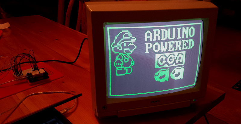
After putting in some sprite data by hand, it is clear the framebuffer works and is ready to use…
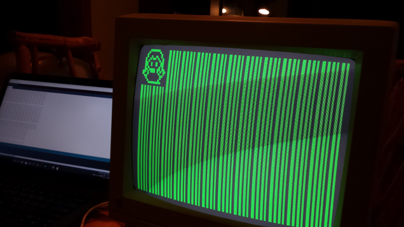
Add a little helper program to churn out relevant byte arrays, and we can have the Arduino draw pretty much anything on the screen!
The code
The complete code is available as a GitHub project under the MIT license: ArduinoCGADriver. Enjoy!